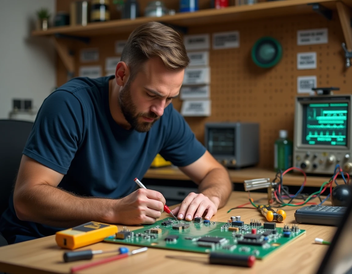
A circuit that won’t light up, a sensor that returns erratic values, an Arduino code that compiles but does nothing visible: most amateur electronics projects stumble on a concrete problem, not a lack of motivation. The choice of the right tools, software, and learning resources often determines the difference between a functional prototype and a setup abandoned at the back of a drawer.
This guide focuses on the lesser-covered levers by traditional tutorials: online simulators, AI-assisted troubleshooting, and methods for structuring your first projects.
Online Simulators for Amateur Electronics: Prototyping Without Hardware
Have you ever wanted to test a schematic before ordering any components? Online simulation platforms meet this need. They allow you to wire a virtual circuit, inject code, and observe behavior in real-time, directly from a browser.
Wokwi simulates Arduino and ESP32 boards with sufficient fidelity to validate a setup before building it. The tool offers common components (LEDs, temperature sensors, servos, OLED screens) and displays the serial console like a real monitor. Tinkercad Circuits, developed by Autodesk, takes a more visual approach: you drag and drop components onto a virtual breadboard, which is well-suited for beginners who have never touched a breadboard.
These environments do not replace a real test bench. Noisy analog signals, wiring interference, or thermal issues do not appear in simulation. Their strength lies in enabling rapid iterations on the logic of a circuit and the associated code. For those discovering Mon Club Elec tools on Spot Emploi, these simulators complement tutorials well by providing an immediate practice ground.

Artificial Intelligence and Circuit Troubleshooting: Practical Use in Workshops
The integration of AI into electronic design is no longer just for professional engineers. Since 2023, experiences shared on Hackaday.io and the r/arduino subreddit document a common practice: submitting a schematic or error message to an AI assistant for diagnostic guidance.
Specifically, a maker stuck on unexpected behavior can paste their Arduino code and symptom description into ChatGPT or Copilot. The assistant suggests leads (wrong variable type, incorrectly declared pin, missing pull-up resistor). This is not a magic solution: the response must always be verified against the component’s datasheet or the official documentation of the microcontroller.
On the PCB design side, software like KiCad is starting to offer routing assistance features. Commercial suites (Altium, Autodesk’s Fusion 360) go further with schematic autocompletion and assisted component placement. For an amateur, KiCad remains the most accessible entry point as it is free and has an active French-speaking community.
Limitations to Keep in Mind
AI does not understand the physical context of your setup. It ignores the length of your wires, the quality of your solder joints, and the actual tolerance of your components. Treating its suggestions as hypotheses to be tested with a multimeter, never as definitive diagnostics, helps avoid wasting time on false leads.
Structuring an Amateur Electronics Project Without Getting Distracted
Many beginners accumulate modules (sensors, screens, relays) without a clear plan, then find themselves facing a tangle of wires and incompatible libraries. Defining the expected outcome before choosing components radically changes the trajectory of a project.
An effective method is to break the project down into independent functional blocks:
- The power block (what voltage, what current, battery or mains) is sized first as it conditions everything else
- The logic block (microcontroller, code, communication protocol) is tested first in simulation before moving to the breadboard
- The interface block (buttons, screen, LEDs, buzzer) is added once the logic works reliably
This modular approach allows testing each layer separately. When a problem arises, you immediately know which block to investigate.
Documenting to Progress
A logbook (even a simple text file) where you note every modification, every error, and every solution found is a more useful personal resource than any generic tutorial. Sharing platforms like Hackaday.io encourage this practice by offering public project journals. Reviewing your own notes three months later saves hours on a similar project.
Choosing Your First Measurement Equipment for Electronic Projects
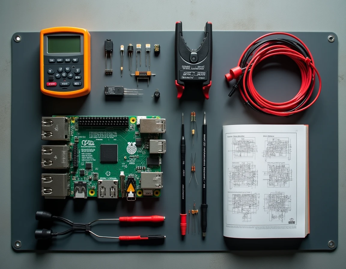
The digital multimeter is the only truly essential instrument to start with. Checking a voltage, testing the continuity of a trace, measuring a resistance: these basic actions help resolve the majority of failures encountered in an amateur setup.
Are you hesitant to invest in an oscilloscope? For Arduino or ESP32-centered projects, a USB logic analyzer costing a few dozen euros often proves more useful. It captures digital signals (I2C, SPI, UART) and displays them on software like PulseView. A logic analyzer detects communication problems between modules much faster than a low-end analog oscilloscope.
- The multimeter covers basic measurements (voltage, current, resistance, continuity)
- The USB logic analyzer decodes serial communication protocols
- The adjustable lab power supply becomes useful as soon as you work with components sensitive to overvoltages
Adding instruments as projects progress, based on actual needs, prevents tying up a budget in equipment that will sit on the shelf.
The best investment in amateur electronics is not the most expensive soldering iron or the latest microcontroller. It’s the time spent understanding why a setup doesn’t work, armed with a multimeter and reliable documentation.